
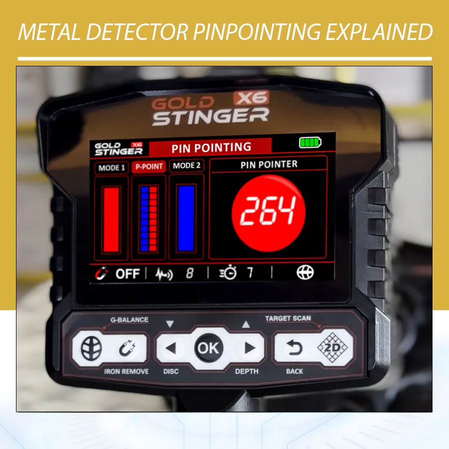
Metal Detector Pinpointing Explained: How to Locate a Target Accurately
Metal detector pinpointing is the process of narrowing a detected response to the smallest practical area before recovery. Good pinpointing helps you dig a smaller opening, spend less time searching loose soil, and reduce the chance of striking a coin, ring, relic, cable, or other object with a digging tool.
Pinpointing does not identify the target or prove its depth. A strong center can belong to a coin, nail, can, several nearby objects, or mineralized material. Accuracy comes from combining controlled coil movement, checks from more than one direction, the correct procedure for your detector, and careful recovery.
This guide explains manual and electronic pinpointing, Double-D and concentric coil behavior, common errors, handheld pinpointers, and practical exercises. Examples from the Gold Stinger X6, Minelab MANTICORE, and Garrett ACE 400i show why the instructions must match the device.

What is metal detector pinpointing?
During ordinary searching, the coil covers an area while the detector reports responses that meet the active mode and settings. Once a response deserves investigation, pinpointing changes the question from “is there something here?” to “where is the center of the response?”
Some detectors provide an electronic pinpoint mode. It may use non-motion operation, meaning the detector continues responding while the coil is held over the target. Some progressively narrow or retune the response. Other detectors use a dedicated target-location system with its own screen values. Manual pinpointing uses the normal search mode and controlled crossing sweeps.
A handheld pinpointer is a separate short-range tool used after opening the ground or removing a plug. It searches the hole, plug, or loose soil. It does not replace the main detector’s wider search coil, and the main detector’s pinpoint button does not replace the close-range convenience of a probe.
Detection, identification, depth, and pinpointing are different tasks
| Function | Question it helps answer | Important limitation |
|---|---|---|
| Detection | Is there a response beneath or near the coil? | A response may come from metal, difficult ground, interference, or several objects. |
| Target identification | What response category does the detector estimate? | Target ID cannot confirm material, purity, value, or exact object type. |
| Depth indication | How does signal strength compare with the model’s calibration? | Object size, orientation, soil, and settings affect the estimate. |
| Pinpointing | Where is the strongest or most centered response? | The response center is not always the physical center of a long or mixed target. |
Keeping these functions separate prevents a common mistake: treating a precise location as precise identification. Pinpoint mode can guide a careful excavation, but it does not turn a detector into an underground camera. Even a narrow, repeatable response still requires recovery or other appropriate evidence.
Why accurate pinpointing matters
Smaller recovery area: a centered response allows a narrow plug or carefully placed excavation where digging is permitted. This saves time and helps restore the surface neatly.
Lower risk of damage: coins and jewelry can be scratched by a shovel or probe. Historic objects may be fragile. Marking the response and opening beside it is safer than driving a tool through the strongest point.
Better diagnosis: a target that appears to move as you cross it may be elongated, tilted, very large, shallow, or accompanied by another object. Pinpointing becomes a way to study the response, not merely a final button press.
More efficient recovery: once the hole is open, knowing the expected center helps you decide whether to search the sidewall, bottom, plug, or loose soil. If the response does not match the expected position, rescan before widening the hole.
How search-coil shape affects the response
Double-D coils
A Double-D coil’s useful detection pattern is often described as a blade or strip running through the central overlap of its windings. In normal searching, this design can provide consistent coverage and useful ground handling. For pinpointing, the strongest response may extend along part of the coil’s centerline instead of forming a single obvious dot.
Cross the target from two directions. The place where the strongest centerline responses intersect is a practical dig reference. Some users also draw the target toward the heel or toe of a DD coil until the response disappears, but the exact exit point depends on coil design and must be learned with known targets.
Concentric coils
A concentric coil is commonly described as having a cone-shaped response that narrows toward the center. A side-to-side and front-to-back cross can work well. Still, a shallow large object may respond across much of the coil, while a deep or small target may produce a limited signal.
Other coil designs
Elliptical shape does not by itself tell you the winding arrangement. Monoloop, specialty imaging, and multi-element coils also behave differently. Use the center or reference point shown by the manufacturer and practise with the exact coil fitted. Do not transfer a video made with another coil as if its physical sweet spot were universal.
Manual cross-sweep pinpointing
Manual pinpointing works in the active search mode and is useful when the detector lacks a dedicated button, when a trashy site makes non-motion mode too broad, or when you want an independent check.
- Confirm the target. Make several ordinary passes and identify the short section where the signal repeats. Avoid starting with a wide, uncontrolled swing.
- Shorten the sweep. Keep the coil level and reduce each pass until you are moving only across the response.
- Mark the first line. Note where the response peaks or where the coil center passes over its most consistent point.
- Turn approximately 90 degrees. Cross the same area from another direction without changing sensitivity or height.
- Mark the intersection. The crossing of the two response lines is your initial recovery reference.
- Check intermediate angles. If the center moves significantly, investigate the possibility of a long object, adjacent targets, sloping ground, or an irregular response.
Keep the coil parallel to the ground. Raising it at the end of each swing changes distance and can make one edge sound weaker for reasons unrelated to target position. A slow, repeatable pass is more informative than waving rapidly until one sound seems loudest.
Electronic pinpoint mode: a careful workflow
Read the manual before treating this as a universal sequence. Many electronic modes share useful principles, but activation, retuning, discrimination behavior, and display information differ.
- Locate the approximate target in search mode. Electronic pinpointing works best after the normal search has already isolated a response.
- Move the coil clear if instructed. Some detectors establish a reference when pinpoint mode is activated. Activating directly over the target can reduce or distort the usable response.
- Activate the mode as documented. Some buttons must be held; others toggle the mode. Watch for the mode indicator.
- Approach slowly at constant height. Listen for increasing volume or pitch and watch the strength bar or numerical display where provided.
- Cross from another direction. A second line reduces the chance that you mark only one part of a long response.
- Retune only as the manual permits. Progressive narrowing can help on a broad target, but repeated retuning can shrink the response too far or make the target seem displaced.
- Exit and reconfirm in search mode. This helps ensure you centered the original target rather than nearby trash.
In a non-motion pinpoint mode, audio may continue when the coil stops. That is expected behavior, not proof that the detector has become unstable. Conversely, ordinary motion search modes may need coil movement to report the target clearly.
Example 1: Gold Stinger X6 Pin Pointer system
The Gold Stinger X6 is a multi-system detector available through Orient Detectors. The Orient listing names All Metals, Discrimination, Pin Pointer, Depth Detection, 2D Target Scan, and Cavity detection, while Stinger’s public page confirms that the X6 has six search systems. Pin Pointer is most useful after another search mode has identified an area that deserves a closer check.
The official Stinger Detectors X6 information describes the GS30 coil as designed for sensitivity, tighter spaces, separation, and pinpoint accuracy, while the GS50 emphasizes wider coverage and larger or deeper targets. That makes coil choice part of the workflow: broad coverage helps find an area; a smaller compatible coil can make closely spaced responses easier to separate.
In the X6 Pin Pointer system, use the location cues provided by the selected system according to the supplied X6 instructions. Treat any displayed values as information within that mode, not universal metal-identification numbers. A larger or shallower object can dominate the response, and ground balance, orientation, and nearby metal can change what appears.
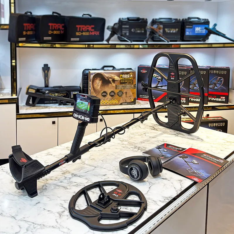
The X6 also includes functions associated with cavities and depth estimation. Keep their questions separate. Pinpointing a metal response does not confirm a cavity, and a cavity-oriented response does not prove an empty chamber or define its boundaries. Use repeated, aligned passes and the correct system rather than combining unrelated screen values into one conclusion.
A practical Gold Stinger X6 sequence
- Ground balance as described for the selected coil and site.
- Search with the appropriate initial system and confirm a repeatable response.
- Mark the approximate center from two directions before changing systems.
- Enter Pin Pointer and use short, controlled passes over the marked area.
- Compare the strongest response with the original cross.
- If the centers disagree, return to the initial mode and look for multiple or elongated responses.
This is an editorial training workflow based on the documented functions, not a claimed field test or a promise that every target will produce a single perfect center.
Example 2: Minelab MANTICORE Pinpoint mode
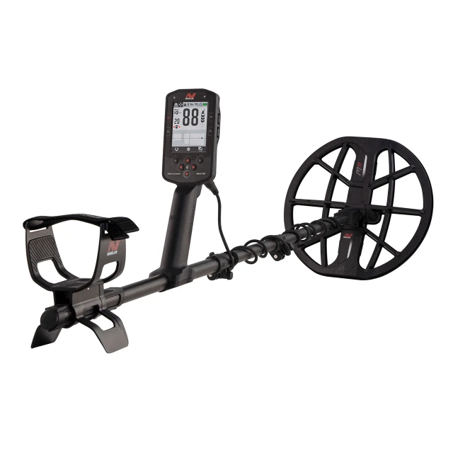
The Minelab MANTICORE provides both manual pinpointing and a dedicated mode. According to Minelab’s current instruction manual, Pinpoint detects targets regardless of the active discrimination pattern and Ferrous Limits and switches off motion detection. Its bar fills toward the center as the coil’s centerline approaches the strongest response.
The documented procedure begins with the coil away from the approximate target before the mode is turned on. Slow passes calibrate the response, and the mode progressively narrows it. Target ID and the 2D map continue updating, which can help check whether the user is centering the intended response rather than adjacent trash. These features do not make the ID chemically certain.
If the mode becomes noisy or difficult to center, Minelab instructs the user to turn it off and restart the procedure. This illustrates why activation position matters: the detector needs a useful reference before it begins narrowing the target.
Consult the official MANTICORE manuals page for the current instructions. The model’s procedure should not be copied onto the Gold Stinger X6 or ACE 400i.
Example 3: Garrett ACE 400i crosshair method
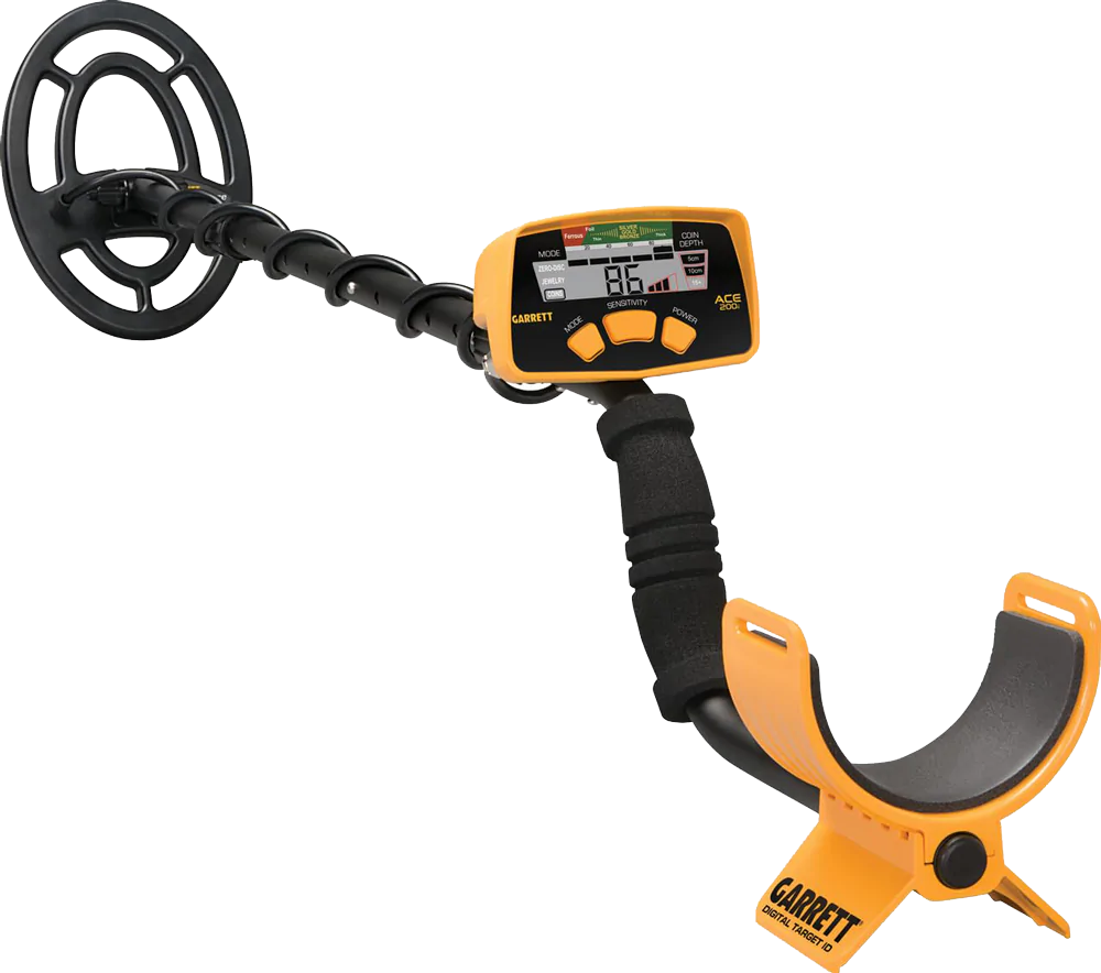
The Garrett ACE 400i offers a clear beginner example. Its pinpoint button is held while the coil is slowly swept over the suspected location at a fixed height. Garrett instructs users to sweep side-to-side and front-to-back, using the loudest sound and the greatest number of upper-scale segments to locate the peak.
The official ACE 400i manual identifies the center of its standard 8.5-by-11-inch coil as the pinpoint reference. It also notes that the depth display is calibrated for a coin-sized target. A large can, small earring, tilted coin, or irregular relic can therefore make the indicated depth misleading.
The useful lesson is transferable even though the exact controls are not: hold a consistent coil height, cross the target, and learn the physical reference point of the fitted coil. Garrett’s general pinpointing guidance also recommends an X pattern and listening for the peak.
Built-in pinpoint mode versus a handheld pinpointer
| Tool | Best stage | Strength | Limitation |
|---|---|---|---|
| Manual cross-sweep | Before digging | Works without changing modes and reveals directional behavior. | Requires controlled movement and coil familiarity. |
| Built-in pinpoint mode | Before digging | Provides a concentrated strength response and may be non-motion. | Nearby targets or poor activation position can broaden or shift the center. |
| Handheld pinpointer | After opening the recovery area | Quickly checks plug, sidewall, hole, and loose soil at close range. | Short range; can respond to soil minerals, tools, or several nearby objects. |
Use the main detector before digging and rescan with it during recovery. Use the handheld probe to reduce handling and find a small object in loose material. After recovery, scan the hole and plug again: the first object may not have produced the only response.
A handheld device can interfere with the main detector when close to its coil. Move it away according to manufacturer guidance rather than assuming switching it off always removes every interaction. Keep digging tools and other carried metal out of the test area as well.
Why the target center can seem to move
Long or irregular objects
A nail, wire, pipe, chain, or elongated relic can produce different peaks along its length. The electromagnetic center may not match the visual center you later see. Crossing from several directions helps reveal an axis instead of a dot.
Multiple nearby targets
A coin beside a nail or two pieces of trash under one coil can blend. The apparent center may shift with sweep direction, recovery setting, or coil position. Return to search mode and listen for separate responses. A smaller compatible coil may improve separation.
Very shallow targets
A shallow large response can overload or sound across a broad portion of the coil. Raise the coil gradually and repeat the cross while keeping it level. This is a location technique, not a calibrated depth test.
Deep or weak targets
A weak response may not give a stable pinpoint center. Mark the most repeatable line, check at right angles, and dig conservatively. Do not increase sensitivity until chatter overwhelms the original signal.
Slopes, rocks, and coil-height changes
If the coil rises over a stone or dips into a hollow, signal strength changes with distance. Marking the point from only one direction may introduce a geometric error. Follow the ground contour without striking the coil.
A careful target-recovery workflow
- Confirm permission and choose an appropriate recovery method. Site rules and surface type determine whether and how you may dig.
- Mark the centered response. Use a nonmetallic marker placed beside the point, not directly where it could be mistaken for the target.
- Move the main coil away. Avoid resting it beside the digging tool or handheld probe.
- Open beside the expected target. Leave a margin so the tool does not cut through the strongest point.
- Rescan the plug and hole. Determine where the response moved before removing more soil.
- Use a handheld pinpointer carefully. Check the sidewalls, bottom, and removed soil without forcing the probe into a fragile object.
- Recover by hand when safe. Wear suitable gloves; sharp metal and glass may be present.
- Scan again and restore the site. A second object may remain, and careful restoration is part of responsible detecting.
Never use a detector response as proof that excavation is safe around utilities, unexploded ordnance, archaeological remains, or hazardous material. Stop and follow the relevant authority or professional procedure when the context suggests those risks.
Three exercises for learning metal detector pinpointing
Exercise 1: map the fitted coil
Place a coin-sized known target on a clean, nonmetallic surface away from reinforced floors. Pass the coil at a consistent height and mark where the signal begins, peaks, and ends. Repeat front-to-back. Draw the response shape and the coil reference point.
Turn the target on edge and repeat. The exercise shows why one memorized center is only a starting point. It does not establish field depth because an exposed target lacks soil effects.
Exercise 2: compare manual and electronic centers
Locate one known target with a manual cross and place two small markers beside the crossing. Then activate the electronic mode exactly as the manual instructs and mark that center. Repeat after leaving and approaching again.
If the marks disagree, check activation position, coil height, target orientation, and surrounding metal. Record the variation rather than moving the marker to make the methods appear identical.
Exercise 3: separate two targets
Place a coin and nail far apart and learn each response. Move them closer in measured steps. Cross from different directions in search mode, then compare pinpoint mode. Note when one apparent center becomes two.
This exercise teaches a crucial limit: precise centering cannot compensate for every masked target. Sometimes search-mode separation and a smaller coil provide more useful information than a broad non-motion response.
A simple pinpointing field log
| Record | Example format | Why it matters |
|---|---|---|
| Equipment | Detector, coil, search mode, pinpoint method | Different coils and modes create different responses. |
| Target response | Short, broad, weak, overloaded, mixed | Describes evidence before guessing identity. |
| Centers | Manual cross, electronic center, recovery point | Measures practical accuracy over time. |
| Recovery result | Object, orientation, adjacent metal, actual location | Connects the detector response with what was found. |
| Site condition | Mild soil, mineralized soil, trash, slope, roots | Explains why the same target may behave differently. |
Common pinpointing mistakes
Activating over the target: on models that set a reference at activation, this can weaken or narrow the response incorrectly. Follow the manual.
Changing coil height: lifting one side or swinging in an arc changes response strength and shifts the apparent peak.
Trusting one direction: an elongated object may sound centered along a line. Cross it and check additional angles.
Confusing loudness with value: a loud shallow can may be easy to center. A faint ring can be harder. Signal strength does not rank worth.
Assuming the depth display is exact: many displays use coin-sized calibration. Large and small objects can appear shallower or deeper than they are.
Ignoring nearby trash: electronic pinpointing may include accepted and rejected objects differently from search mode. Reconfirm the original response.
Widening the hole without rescanning: the object may already be in the plug or sidewall. Rescan after each controlled step.
Using a handheld probe as a digging tool: probing forcefully can damage the target or the device. Use it to locate, then recover carefully.
How to improve pinpointing accuracy over time
Practise first with common targets whose positions are known. Use the same coil and mode you plan to take into the field. Learn where the fitted coil produces its strongest response instead of relying only on a printed center mark.
Keep your method consistent: confirm, shorten the sweep, cross, activate the correct mode, and reconfirm. Change one variable at a time. If a smaller coil improves separation, record that result without turning it into a universal claim about depth.
Judge accuracy after recovery. The distance between the predicted center and actual object teaches more than a perfect-looking strength bar. Over time, your notes will reveal whether errors occur with nails, deep coins, shallow cans, slopes, or a particular activation habit.
Effective metal detector pinpointing is therefore a repeatable process rather than a single feature. The best method is the one you understand, can reproduce, and can verify through careful recovery.
Frequently asked questions
1. What is metal detector pinpointing?
It is the process of narrowing a detected response to the smallest practical recovery area. It can use manual crossing sweeps, a built-in electronic mode, and a handheld pinpointer after digging begins.
2. Does pinpoint mode identify the metal?
No. It primarily helps locate response strength. Some screens continue showing classification information, but this remains an estimate and cannot confirm composition, purity, or value.
3. Why should I activate pinpoint away from the target?
Some detectors establish a response reference when the mode starts. Activating over the target can detune or narrow it incorrectly. Follow the instructions for your model because activation behavior differs.
4. Where is the pinpoint center on a Double-D coil?
It is commonly associated with the central overlap or centerline, but the useful response can extend along that line. Cross from two directions and practise with the exact coil rather than assuming one universal spot.
5. Why does the pinpoint center move?
Possible causes include an elongated target, nearby metal, changing coil height, a broad shallow object, weak depth response, or incorrect mode activation. Return to search mode and compare directions.
6. Is a handheld pinpointer necessary?
No, but it can make recovery faster by checking the plug, hole, sidewall, and loose soil at close range. The main detector should still establish the recovery location first.
7. Can pinpointing tell exact depth?
No. A depth indicator is generally an estimate based on response strength and a reference target. Object size, shape, orientation, soil, and settings can change it substantially.
8. Which Gold Stinger X6 coil is better for pinpointing?
Stinger describes the GS30 as the precision-oriented coil and the GS50 as suited to wider coverage and larger or deeper targets. The best choice depends on the target, spacing, ground, and search stage.
9. Should I use pinpoint mode in heavy trash?
Use it carefully. A non-motion or broad strength response may blend adjacent objects. First separate signals in search mode, cross them, and consider a smaller compatible coil.
10. How can I avoid damaging a target?
Mark the center, open beside it with a margin, rescan the plug and hole, and use a handheld probe gently. Do not drive a digging tool through the strongest response point.
Resources
- Stinger Detectors: Gold Stinger X6 — official system and coil overview.
- Orient Detectors: Gold Stinger X6 — catalogue page for the featured multi-system detector.
- Minelab product manuals — current MANTICORE pinpoint instructions.
- Garrett ACE 400i owner’s manual — electronic crosshair pinpoint procedure.
- Garrett detecting FAQ — general manual X-pattern guidance.
- Orient Detectors: Target ID Guide — why location and identification should be interpreted separately.