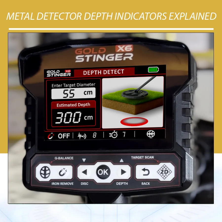
A metal detector depth indicator estimates how far a detected target may be below the search coil. It can help you plan a neat recovery, choose the right digging tool, and recognize when a target may be larger or smaller than expected. The reading is useful, but it is not a direct measurement of the object’s position.
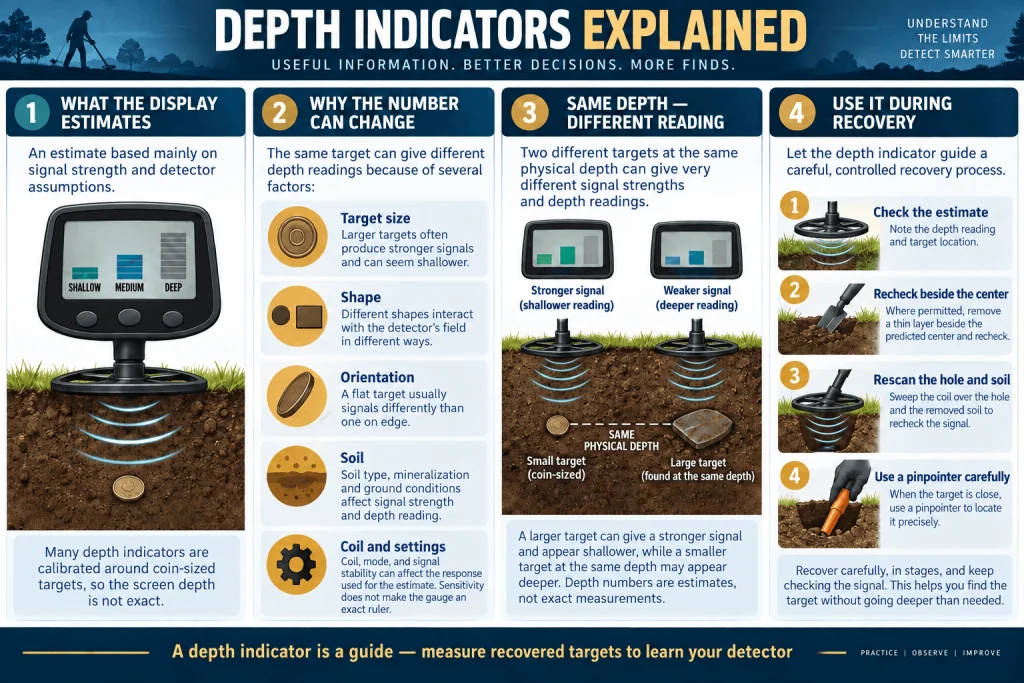
Most visual depth systems interpret signal strength through assumptions programmed by the manufacturer. Many coin and treasure detectors are calibrated around a coin-sized reference target in relatively favorable ground. A different object can produce the same signal strength from a different physical depth. Soil, target angle, coil height, nearby metal, settings, and mineralization can shift the estimate again.
This guide explains what the gauge can tell you, what it cannot prove, and how to check it before digging. It includes documented examples from the Minelab MANTICORE, Minelab EQUINOX 900, and Garrett ACE 400i, all represented in the Orient Detectors catalog. The examples show why every scale must be read according to its own manual rather than converted into a universal rule.
What does a metal detector depth indicator measure?
A detector evaluates the response returning to the coil. Generally, a nearby target produces a stronger response than an identical target farther away. The detector compares that response with its calibration and shows a depth band, arrows, bars, or an approximate distance.
The important word is estimate. The instrument does not send a ruler through the soil. If the software assumes a coin-sized reference, a large plate can create a strong response from much farther away, while a tiny earring may give a weak response when comparatively shallow.
Depth usually means distance from the coil rather than the visible surface. Grass, stones, stubble, uneven terrain, and an arcing sweep can change the display through the added air gap.
How common depth displays present the estimate
Manufacturers use bars, arrows, a coin-depth scale, or an approximate distance. Some displays refresh during motion search; others are easier to interpret after centering or in electronic pinpoint. A model may retain the last reading briefly.
| Display style | What it communicates | Best way to use it | Main caution |
|---|---|---|---|
| Bars or arrows | A shallow-to-deep band | Compare repeated centered sweeps | A bar is not a universal distance |
| Coin-depth marks | Estimated depth for a coin-sized target | Plan recovery of compact targets | Large and tiny objects can misread |
| Numeric distance | An approximate distance under calibration assumptions | Treat it as a digging guide | The number can look more exact than it is |
| Signal-strength display | Relative response near the target center | Use with pinpointing and coil control | Strength is affected by size and orientation |
Never transfer marks from one machine to another. Five levels may use different boundaries. Consult the manual for the exact model and software version.
Why many gauges are calibrated to a coin-sized target
A manufacturer needs a consistent reference to turn response strength into an understandable depth scale. A coin is compact, repeatable, familiar to hobby detectorists, and easy to use during development. The MANTICORE and EQUINOX 900 manuals illustrate their gauges using a US quarter. Garrett describes the ACE 400 and ACE 400i feature as a Coin Depth Indicator for a coin or similarly sized target.
This calibration suits many compact finds. It does not mean the gauge recognizes a coin. Target ID and depth are separate interpretations, and neither provides certain identity.
The reference also explains predictable errors. Garrett states that a target larger than a coin may display shallower than its actual depth, while a smaller target may display deeper. The larger object returns more energy than the reference target would at the same location, so the detector interprets it as closer. The small object returns less and may be interpreted as farther away. This is a useful model for thinking, although the exact behavior still depends on the detector and target.
Target size can change the reading dramatically
Signal strength is not determined by distance alone. A large lid, can, pipe, tool, or sheet of metal can remain detectable at a distance where a coin would produce little or no usable response. If the algorithm treats that strong return as coin-like, the screen can indicate a shallow target even though the object is deeper. The broad response may extend across a long sweep and remain strong when the coil is raised, providing clues that the object is large.
A tiny target creates the opposite problem. Fine jewelry, a small hammered coin, thin foil, a pellet, or a narrow fragment may sound weak at modest depth. The gauge can place it in a deeper band because the response resembles a farther-away reference coin. The reading does not mean that the object must be deep; it means the received signal falls into that strength range under the detector’s processing.
As a supporting check, center the response and raise the coil gradually. A broad signal that remains strong well above the ground may suggest a larger target, although elongated iron and multiple objects can complicate the result.
Shape, orientation, and conductivity affect the estimate
A flat coin presents a different electromagnetic profile from the same coin on edge. A ring, chain, irregular relic, folded can, nail, and hollow container couple with the transmitted field differently. Orientation can make the effective response area larger or smaller, and it can change as the coil approaches from another direction. A coin lying flat may give a stronger, more consistent estimate than the same coin nearly vertical.
Conductivity and magnetic behavior also affect the received signal and the detector’s classification. A high-conductive object does not automatically read at the correct depth, nor does a low-conductive reading mean an object is deep. Frequency choice, simultaneous multi-frequency processing, mode, and target composition all influence the response that reaches the depth algorithm.
Recheck from ninety degrees. If the apparent depth, audio width, or Target ID changes greatly, suspect orientation, shape, adjacent objects, or difficult ground. A stable two-way reading still does not guarantee identity, but it gives you a better-centered and more repeatable estimate for planning the recovery.
Soil and mineralization can reduce accuracy
The signal travels through the local environment twice: from coil toward target and back toward the receiving system. Mineralized soil, black sand, salt, hot rocks, moisture patterns, and abrupt ground changes add their own responses. The detector must separate target information from that background. The MANTICORE and EQUINOX 900 manuals explicitly say depth accuracy is reduced in highly mineralized soil.
Ground balance cannot remove every mineral effect. Select the appropriate mode, follow the documented balance procedure, and adjust sensitivity for stability. Continuous chatter makes a precise-looking mark less trustworthy.
Moisture can change signal coupling or salt response, so record site conditions. The Orient Detectors Metal Detector Ground Balance Guide explains why balancing the machine should come before interpreting advanced display information.
Coil height is part of the apparent depth
The display responds to target-to-coil distance. Suppose a compact target is buried 10 centimeters below a smooth surface. With the coil 2 centimeters above the ground, the physical gap to the target is already about 12 centimeters before angle and soil effects are considered. Raise the coil over tall grass and the indicated band can move deeper.
Keep the coil low, level, and at a consistent height during the confirming sweeps. Avoid lifting at the ends of the arc. On rough ground, make shorter overlapping sweeps that follow the surface safely. If vegetation prevents a close pass, treat the gauge as a relative clue and allow for the air gap.
Coil design and size matter as well. A larger coil can produce a different response footprint and response strength from a small coil over the same object. A small coil may isolate a target better in trash. If you change coils while maintaining a test garden, record which coil produced each result. Do not assume the old depth bands will behave identically.
Sensitivity changes detection, not the ruler
Sensitivity controls how strongly the detector responds to input or how much signal variation it makes available for processing, depending on the design. It is not a calibration knob that makes the depth display physically exact. Raising sensitivity may help a faint target become detectable, but it can also admit more electromagnetic interference and ground noise. An unstable machine may provide less useful target and depth information.
For a repeatable check, begin with a stable sensitivity level. Noise-cancel or shift frequency according to the manual, ground balance where appropriate, and then center the target. If you change sensitivity, repeat the same path, height, and sweep pace. Note whether the target becomes more repeatable rather than celebrating a deeper-looking bar.
Sensitivity numbers are not comparable across detectors. Compare reliable recognition of the same known target, then check each indicator against measured recovery depth.
Pinpoint mode and depth estimation
Accurate centering improves the reading because the target response normally peaks under a particular part of the search coil. During an off-center sweep, the signal may be weaker and appear deeper. Electronic pinpoint mode can help locate that peak. The Garrett ACE 400i manual directs the user to hold Pinpoint, keep a fixed coil height, sweep side-to-side and front-to-back, and use the loudest response and greatest number of upper-scale segments to locate the center.
On the ACE 400i, the Coin Depth Indicator can be viewed during this process. That is useful for recovery planning, but Pinpoint does not identify target size or eliminate mineralization. A broad, persistent response may still belong to large metal, and two close objects may create a combined center between them.
Use the Metal Detector Pinpointing Guide to refine cross-sweeps, coil-edge methods, and handheld pinpointer technique. Once the plug or excavation is open, a handheld pinpointer can locate the object in the soil wall or removed material. Its job is precise local recovery; it does not validate the original screen estimate.
Multiple targets, masking, and rejected objects
Two nearby objects can create overlapping responses. The detector may emphasize the stronger target, combine parts of both signals, or report changing information as the coil moves. A coin near a nail might appear at an unstable depth from one direction and disappear from another. Two coins can sound like one broader object. Trash above a deeper target can dominate the depth estimate.
Discrimination adds another layer. The current MANTICORE manual says no depth indication is given when a detected target is masked by the Discrimination Pattern or Ferrous Limits. That documented behavior matters: a missing gauge does not prove that no metal exists. It can mean the detected response is being rejected by the active classification settings.
Check from several directions and, where suitable, compare a less restrictive view according to the manual. Shorten the sweep over each suspected center; a smaller coil may help. Metal Detector Target ID Explained provides more context; neither ID nor depth should be used alone.
Overload and extremely strong responses
A very large or very shallow target can exceed the normal signal range. Some detectors issue an overload sound or symbol; others compress the response, display a shallow indication, or become difficult to center. The result is not a reliable depth measurement. Move the coil higher and repeat. If the response remains powerful over a wide area, consider large or elongated metal, multiple objects, or nearby infrastructure.
Do not dig around suspected pipes, cables, irrigation hardware, or structural metal. Confirm permission, check utility information, and stop if the context suggests buried services. A hobby detector cannot certify excavation safety.
Overload also teaches an important lesson: the gauge is designed for a working signal range. Once the signal lies outside that range, an attractive numerical display would not create accuracy. Reduce the response through coil height only as a diagnostic step and use the target’s width, repeatability, surroundings, and safe-site knowledge to decide what to do.
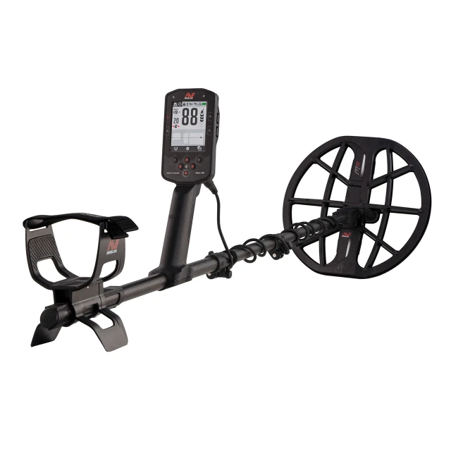
Documented example: Minelab MANTICORE
The Minelab MANTICORE review at Orient Detectors covers a current advanced detector with a five-level Depth Indicator. Minelab’s instruction manual calls it a guide only. Fewer arrows represent a shallower target and more arrows a deeper one. The reading remains briefly after detection or until another target is detected.
The manual illustrates approximate levels for a US quarter in benign soil. Those example distances belong to that stated target and condition; they are not promises for jewelry, relics, iron, mineralized ground, or different coil height. Minelab expressly notes that accuracy can vary with target type and ground conditions and is reduced in highly mineralized soil.
MANTICORE also demonstrates why screen systems must be interpreted together. Its 2D ID Map presents conductive and ferrous information, while the depth arrows communicate an approximate distance class. A faint trace, Target ID, audio response, and depth indication each answer a different question. Use repeatability and centered sweeps to plan the dig. Do not infer that five arrows identify a valuable deep coin.
Documented example: Minelab EQUINOX 900
The current EQUINOX 700/900 manual identifies its five-level Depth Gauge as an EQUINOX 900 feature. The EQUINOX listing at Orient Detectors represents the family; buyers should confirm the exact model and package before relying on a particular feature.
Minelab says the gauge indicates approximate target depth and is a guide only. Its example uses a US quarter, with fewer arrows for shallower and more for deeper. The gauge remains visible for a short period after detection, then clears when there is no detection. As with MANTICORE, target type and ground conditions affect accuracy, and highly mineralized soil reduces it.
The model is a good reminder to read footnotes. Features can vary within a product family, and a website phrase such as “EQUINOX detector” is not enough to establish that every version has the same display. Match the manual to the model name shown on the control unit and note the installed software when conducting a formal comparison.
Documented example: Garrett ACE 400i
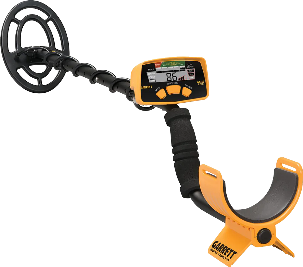
The Garrett ACE 400i uses a Coin Depth Indicator. Its manual describes the target as coin-sized and shows how centering in Pinpoint supports the reading. Garrett’s ACE 400 documentation provides the key limitation plainly: targets larger than a coin may display shallower than actual depth, while targets smaller than a coin may display deeper.
This makes the ACE system an excellent teaching example. A four-inch mark is not a claim that every object is exactly four inches below the soil. It is the detector’s coin-referenced interpretation of the received signal. A large buried can, a small earring, an angled token, or two close targets can disagree with the scale for understandable reasons.
Keep the coil at the fixed height recommended by the manual while pinpointing. Locate the strongest center through cross-sweeps, look at the depth scale, and choose the smallest practical plug or excavation method allowed at the site. Recheck the hole and removed soil after recovery in case more than one object contributed to the original response.
Factors that can move a depth reading
| Factor | Possible display effect | Useful field check |
|---|---|---|
| Large target | May appear shallower | Raise the coil and assess response width |
| Very small target | May appear deeper | Center carefully and compare directions |
| Edge-on or irregular shape | Weak or changing estimate | Rotate sweep direction ninety degrees |
| Mineralized or salty ground | Reduced accuracy or unstable level | Use proper mode and ground balance |
| High coil above ground | Target appears farther away | Maintain a low, constant safe height |
| Nearby target | Combined, missing, or shifting reading | Shorten sweeps and try another direction |
| Electrical interference | Unstable or false information | Noise-cancel and reduce instability |
| Overload | Shallow, saturated, or unusable reading | Raise coil and assess safety/context |
How to field-check your detector’s gauge
A test garden converts general advice into knowledge about your own machine. Use a safe, permitted area free of buried utilities. Record representative target material, dimensions, orientation, measured depth, soil condition, coil, mode, sensitivity, ground balance, and date. Include a coin similar to the manual’s reference, then add a smaller item, a larger item, an angled target, and a nearby-target layout.
Approach each target from at least two directions with the same coil height and sweep pace. Record the depth level only after centering. Repeat under stable settings before changing one variable. If you change the coil, mode, sensitivity, recovery speed, or discrimination, label the new trial rather than mixing results.
Freshly buried targets do not reproduce years of soil settlement, corrosion, moisture movement, and ground conditions. The garden remains valuable for checking display logic, operator consistency, and relative change. The Orient Detectors guide How to Build a Metal Detector Test Garden explains target spacing, control holes, mapping, and safe documentation.
| Record | Example entry | Why it matters |
|---|---|---|
| Target | Known coin, flat | Defines size and orientation |
| Measured cover | Measure from surface to target | Provides the physical comparison |
| Detector setup | Model, coil, mode, settings | Makes the trial repeatable |
| Ground | Dry, moist, mild, mineralized | Explains environmental variation |
| Reading | Level from two directions | Shows stability and directional change |
| Recovery result | Measured target location | Tests the estimate against reality |
Using the indicator during a careful recovery
- Confirm permission and excavation safety. Avoid protected sites and suspected utilities.
- Stabilize the detector. Use the appropriate mode, noise procedure, ground balance, and practical sensitivity.
- Check repeatability. Sweep from two directions and note audio, ID, and apparent width.
- Center the response. Use short cross-sweeps or the documented pinpoint procedure at constant coil height.
- Read the depth as a range. Plan the initial plug or excavation without treating the mark as exact.
- Protect the target. Cut or dig away from the estimated center, especially where valuable coins or relics may be fragile.
- Use a handheld pinpointer carefully. Check the plug, loose soil, and sidewalls before enlarging the hole.
- Re-scan. Confirm that no second object produced part of the original response.
- Measure if documenting a test. Record actual depth and orientation before moving the object.
- Restore the site. Refill cleanly and follow local rules.
This workflow uses the gauge for what it does well: estimating effort and supporting a controlled recovery. It also protects against its weaknesses by centering, cross-checking, and measuring only after the object is exposed.
Common mistakes when reading target depth
The most common mistake is treating apparent precision as certainty. A six-inch display may group a range and apply coin calibration. Report indicated depth separately from physical depth measured during recovery.
Another mistake is using depth to decide value. Deep targets can be modern trash, and shallow targets can be old if erosion, landscaping, plowing, or soil removal changed the site. Depth is context, not a date. Likewise, a stable shallow indication does not prove the object is a coin.
Users also forget coil height, read while off-center, change several settings at once, or compare unrelated scales across brands. Some dig directly into the predicted center and damage the object. Others stop after retrieving one shallow item even though a deeper target contributed to the signal. A deliberate re-scan solves many of these problems.
Depth indicator, Target ID, and audio answer different questions
Depth information estimates target-to-coil distance under assumptions. Target ID estimates conductive or ferrous characteristics. Audio communicates strength, timing, shape, rejection, and stability according to the active audio setup. None is a ground-truth label. Their value comes from agreement, disagreement, and repeatability.
A repeatable compact response with consistent ID and depth from two directions can support a tidy recovery plan. A broad response that reads shallow, stays strong with the coil raised, and spans a large area may suggest larger metal. A one-way response with jumping ID and changing depth near iron calls for another angle, shorter sweeps, or a smaller coil. These are hypotheses to test, not guaranteed identifications.
Learn the channels separately in controlled conditions, then combine them. The Metal Detector Audio Tones guide explains sound, while the Target ID guide explains numerical classification. During every comparison, keep the difference between detection, classification, depth estimation, and final recovery clear.
Frequently asked questions
Are metal detector depth indicators accurate?
They can provide useful approximate guidance, especially for a centered target similar to the manufacturer’s calibration target in favorable ground. Accuracy changes with target size, shape, angle, soil, coil height, settings, mineralization, and nearby metal. Treat the result as a range for recovery planning.
Does the depth number measure from the ground surface?
The detector responds to distance from the coil. Any air gap caused by grass, stones, stubble, or an elevated sweep contributes to that distance. Keep coil height consistent and allow for the gap when interpreting the screen.
Why does a large target read shallow?
A large object can produce a stronger response than a coin-sized calibration target at the same depth. The detector may interpret that extra strength as shorter distance. Garrett explicitly documents this behavior for the ACE 400.
Why does a tiny target read deeper than it is?
A small object may create a weaker response than the reference target. Its signal can resemble that of a coin located farther from the coil, causing a deeper indication. Careful centering and recovery reveal the real position.
Can a depth indicator tell whether the target is valuable?
No. It estimates distance rather than value, age, or identity. Modern trash can be deep and valuable objects can be shallow. Use audio, Target ID, site context, and lawful recovery together.
Does maximum sensitivity make the depth reading more accurate?
No. Excessive sensitivity can increase ground noise and electromagnetic interference, making information less stable. Use the highest setting that remains suitably stable for the site and follow the manufacturer’s setup procedure.
Should I read depth in normal search or Pinpoint mode?
Follow the exact manual. Some gauges update in normal detection, while a centered Pinpoint response can help certain models provide a more useful reading. Pinpointing improves location but does not remove calibration limitations.
Why does the depth indication change with sweep direction?
The target may be angled or irregular, or another object may overlap its signal. Coil geometry and soil variation can also contribute. Recenter from both directions and treat a large disagreement as evidence that the target situation is complex.
Why is there no depth reading over a signal?
The signal may be too weak, unstable, rejected, overloaded, or outside the gauge’s normal behavior. On MANTICORE, Minelab states that a target masked by the discrimination pattern or Ferrous Limits does not receive a depth indication.
Can I compare the depth bars on two different detectors?
Only through a controlled test with known targets. The number of bars or arrows does not establish equivalent calibration. Keep target, soil, coil height, sweep, and relevant settings consistent, then compare each result with measured recovery depth.
Final perspective
A metal detector depth indicator is most valuable when treated as a calibrated estimate rather than a promise. It can tell you that a centered, coin-like response appears relatively shallow or deep under the current conditions. It can help determine plug size, tool choice, and the care needed during recovery. It cannot independently identify the object or measure its exact burial depth.
Read the scale for your exact model, maintain consistent coil height, center from more than one direction, and consider target size, orientation, soil, settings, and nearby metal. Build a documented test garden and compare displayed estimates with measured recoveries. With practice, the gauge becomes a useful part of a larger evidence set that includes audio, Target ID, response width, site context, and careful excavation.