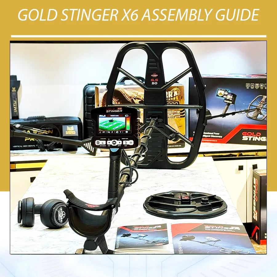
Parts Needed for Gold Stinger X6 Assembly
Place the control box, upper shaft, middle shaft, lower shaft, selected coil, coil connection cable, arm strap and mounting hardware in front of you. Keep the second coil protected until it is needed. Confirm all parts against the Gold Stinger X6 package contents guide.
| Part | Role | Check before installation |
|---|---|---|
| Control box | Houses display, keypad and electronics | Mounting points, screen, ports and power switch |
| Upper shaft | Supports control box and arm position | Straightness and mounting hardware |
| Middle shaft | Provides length adjustment | Locks and smooth insertion |
| Lower shaft | Connects the shaft to the coil | Coil-mounting end and adjustment points |
| GS30 or GS50 | Searches the ground | Coil shell, ears, cable entry and connector |
| Coil screw and nut | Secures coil angle | Correct parts and supplied washers |
| Connection cable | Links coil and control unit | Pins, threads, cable and strain relief |
| Arm strap | Stabilizes the detector | Stitching, fastener and adjustment range |
Prepare a Safe Assembly Area
Use a dry table or clean floor with enough room to lay the full shaft down. Keep sand, mud and metal filings away from connectors. Soft padding under the control box and coil prevents scratches. Good lighting makes connector alignment easier.
Remove jewelry or tools that could scratch the display. Do not assemble beside a charging cable connected to power. If the detector arrived from a very cold or hot environment, allow it to reach normal room temperature before charging or operation.
Step 1: Attach the Control Box to the Upper Shaft
Position the control box on the upper shaft exactly as shown in the manual. Align the mounting points before inserting the specified screw. The box should sit straight relative to the handle and armrest. If the holes do not align naturally, recheck orientation rather than forcing the screw.
Secure the box firmly enough that it does not move during normal sweeping. Excessive torque can damage plastic mounts or threads. After tightening, support the shaft and apply only gentle hand pressure to confirm that the control unit does not wobble.
Step 2: Join the Middle and Upper Shafts
Insert the middle shaft into the upper shaft. Align the locking or adjustment mechanism and slide the parts together without impact. Dirt inside a shaft can scratch surfaces and prevent secure locking, so clean dry contamination before insertion.
Do not set final length yet. Leave enough adjustment for the lower shaft and selected coil. Confirm that the joint resists rotation when locked.
Step 3: Insert the Lower Shaft
Slide the lower shaft into the middle section and align the adjustment positions. The coil-mounting end must face the correct direction so that the search coil will lie flat when attached. Lock the shaft at a provisional length.
A common mistake is extending the detector too far. Final shaft length should let the user stand upright, keep the elbow slightly bent and sweep with the coil level. Excess length increases leverage on the wrist and shoulder.
Step 4: Choose the GS30 or GS50 Coil
Choose the coil according to the site before installation. GS50 favors wider coverage and the manufacturer’s larger/deeper-target priority. GS30 favors small targets, clutter, restricted spaces and easier maneuverability. The dedicated GS30 vs GS50 comparison explains the tradeoffs.
| Search condition | Starting coil | Reason |
|---|---|---|
| Open field with few obstacles | GS50 | Wider coverage |
| Closely spaced metal | GS30 | Narrower target footprint |
| Small-target priority | GS30 | Manufacturer-stated small-target sensitivity |
| Large-target survey | GS50 | Larger/deeper-target priority |
| Rocks, bushes or restricted movement | GS30 | Better maneuverability |
| Uncertain site | GS50 survey, GS30 confirmation | Combines coverage and localization |
Step 5: Attach the Search Coil
Position the lower shaft between the coil mounting ears with any supplied washers or spacers in their correct places. Align the holes without spreading the ears. Insert the specified coil screw and secure it with the correct nut.
Tighten until the coil holds its angle during a sweep but can still be adjusted deliberately by hand. Overtightening can stress the ears; undertightening allows the coil to flop and change height. Never substitute an arbitrary metal bolt near the detection coil.
Step 6: Set the Initial Coil Angle
Place the assembled shaft in the normal operating position and rotate the coil until its face is parallel to level ground. The angle should be judged while the operator holds the detector, not while it lies flat on a table.
On a slope, the user must actively follow the terrain while maintaining consistent clearance. The coil joint should hold the chosen angle without being rigidly locked. Recheck it after several practice sweeps.
Step 7: Connect the Cable at the Coil
Inspect the coil-base connector and cable plug. Identify the alignment features and insert the connector straight. The manual instructs the user to secure it by rotating the specified button section clockwise. Turn the locking portion, not the cable.
If the connector stops before seating, withdraw it and inspect orientation. Forcing a plug can bend pins or damage threads. Keep connector surfaces clean and dry.
Step 8: Route the Cable Around the Shaft
Leave a small relaxed loop at the coil joint so the coil can change angle without pulling the cable. Then wrap the cable evenly around the lower and middle shafts. The wraps should prevent movement but must not be tight enough to kink the cable.
A loose loop near the coil can enter the electromagnetic field and create false responses. An overly tight wrap can stress the internal conductors as shaft length changes. After routing, move the coil through its normal angle range and confirm that the cable does not stretch.
| Check | Correct result | If incorrect |
|---|---|---|
| Coil pivot | Small relaxed loop | Rewrap with additional slack |
| Lower-shaft wraps | Even and secure | Remove loose loops |
| Shaft adjustment | Cable remains relaxed | Reset length and wrap |
| Connector strain | No sideways pull | Realign the cable path |
| Sweep test | No cable movement near coil | Secure the wraps |
Step 9: Connect the Cable to the Control Unit
Align the device-end connector with the control-box socket and insert it straight. The manual describes securing this end by rotating the metal locking section clockwise. Stop if the threads resist or the plug appears angled.
Route the final cable section so it does not interfere with the grip, keypad or headphone jack. Do not create a tight bend immediately below the connector. Confirm that the cable will not be pulled when the shaft is extended.
Step 10: Fit and Adjust the Arm Strap
Thread the arm strap through its support and place the forearm in the armrest. Adjust it so the detector remains controlled when the hand relaxes slightly. The strap should not restrict circulation or trap bulky clothing.
A properly adjusted strap reduces wrist rotation and helps keep the coil level. Recheck it after changing from GS30 to GS50 because the balance and leverage change.
Set the Correct Shaft Length
Stand upright in normal footwear and hold the grip comfortably. Adjust the shaft until the coil rests close to the ground with a slight elbow bend. During a sweep, it should stay parallel and approximately within the manual’s recommended 5–10 cm working range without shoulder lifting.
Test short overlapping arcs. If the coil rises at both ends, shorten the shaft or reduce the sweep width. If it strikes the ground at the center, adjust length and coil angle. Good ergonomics improve both comfort and signal consistency.
Power-On and Coil Connectivity Test
Once assembly is complete, move outdoors away from large metal and electrical interference. Turn the detector on using the rear switch and allow the startup bar to finish. Check the status-bar coil-connectivity indicator.
If Connected appears, continue to ground balance. If Disconnected or Error appears, power off before touching the connector. Inspect both ends, confirm correct seating, reconnect and restart. Do not repeatedly tighten a misaligned plug.
The official Device Startup video shows the transition from assembled detector to initial operation.
Ground Balance After Assembly
Assembly is not complete operationally until the installed coil has been balanced to the search ground. The manual directs the user to the Ground Balance screen at startup. Use a metal-free outdoor patch and maintain a controlled 5–10 cm relationship with the ground while following the calibration motion.
If the screen shows Not OK, move to a clean location, reduce Sensitivity in difficult soil and repeat. Do not diagnose coil performance through indoor air tests while Ground Balance is incomplete.
Changing from GS50 to GS30
- Switch the detector off.
- Lay it on a clean padded surface.
- Release the control-box connector by its locking section.
- Unwrap the cable without pulling it.
- Disconnect the coil end and remove the mounting hardware.
- Support the coil ears while withdrawing the screw.
- Install the second coil with the correct hardware.
- Route and connect its cable.
- Power on and verify coil connectivity.
- Perform a fresh ground balance and establish stable settings.
Record different stable Sensitivity and Turbo values for each coil. The larger GS50 may require more conservative settings in mineralized or electrically noisy ground.
Common Gold Stinger X6 Assembly Mistakes
| Mistake | Possible effect | Correction |
|---|---|---|
| Control box mounted at an angle | Poor balance and difficult screen viewing | Realign before tightening |
| Shaft extended too far | Fatigue and coil lifting | Shorten for a relaxed elbow |
| Coil screw overtightened | Stress on mounting ears | Use only enough tension to hold angle |
| No slack at coil pivot | Cable strain during angle changes | Rewrap with a relaxed loop |
| Loose cable near coil | False signals from cable movement | Secure even wraps |
| Connector forced | Damaged pins or threads | Stop and realign |
| Coil changed while powered | Connection or recognition problems | Power off before changes |
| No ground balance after coil change | Unstable or misleading responses | Balance the installed coil outdoors |
Transporting an Assembled Gold Stinger X6
For short transport, collapse the shaft only if the cable has enough slack to accommodate the change. Do not force a fully wrapped cable along a shortening shaft. Protect the screen and coil from impacts and do not carry the detector by the coil cable.
For longer transport, detach the coil and control unit if the approved case or packing method requires it. Fit connector protection where supplied. Keep the charger, hardware and headphones in separate padded compartments so they cannot strike the display.
Ergonomic Tuning After Gold Stinger X6 Assembly
Mechanical assembly is complete only when the detector fits the operator. The upper shaft, arm strap and coil angle should let the coil glide over the ground with minimal wrist rotation. A poor fit often looks like an electronics problem because coil height changes create unstable responses.
Start with the shaft slightly shorter than expected. Stand normally, lower the coil to the search height and sweep a narrow arc. Lengthen only until the coil reaches the furthest point without lifting the shoulder. The arm strap should support the forearm while still allowing the hand to release the grip safely.
| What you notice | Likely adjustment | Why it helps |
|---|---|---|
| Coil lifts at the sweep ends | Shorten shaft or narrow the arc | Keeps the coil at a consistent height |
| Coil strikes ground at center | Lengthen slightly or change coil angle | Prevents impact noise and abrasion |
| Wrist turns inward | Reposition strap and shaft length | Reduces fatigue and coil tilt |
| Armrest moves during sweep | Tighten strap or control-box mount | Maintains stable geometry |
| Cable pulls at full extension | Rewrap with more pivot slack | Protects the connector and cable |
Static and Dynamic Assembly Tests
Run a static check before powering on, then a dynamic check after Ground Balance. The static check confirms physical security. The dynamic check reveals whether a cable, coil angle or loose lock changes during normal motion.
- Hold the detector by the grip and gently move the coil through its intended angle range.
- Check that cable slack remains relaxed and connectors do not move.
- Apply light sideways pressure to shaft joints; there should be no unwanted rotation.
- Power on outdoors and confirm coil connectivity.
- Complete Ground Balance on clean soil.
- Sweep an empty patch with smooth overlapping arcs.
- Listen for responses caused by cable motion or coil impact.
- Rescan a known target from two directions before adjusting settings.
If the detector creates a response only when the cable flexes or the coil taps the ground, address assembly first. Raising Sensitivity, Turbo or volume will not solve a mechanical false signal.
Assembly Changes That Require a New Setup
Any change that affects the coil or shaft geometry should trigger a quick setup review. Examples include changing from GS30 to GS50, extending the shaft, replacing mounting hardware, rerouting the cable or moving from dry soil to a very different location. Confirm connections, run Ground Balance and find a stable Sensitivity baseline again.
Record the coil, shaft length and stable settings in a simple notebook. This allows a user to restore a proven configuration instead of guessing after transport or a coil change.
Assembly Maintenance Schedule
| When | Check | Action |
|---|---|---|
| Before every search | Coil screw, locks, cable and connectors | Secure, clean and confirm relaxed cable path |
| After every search | Coil shell, shaft and cable | Remove dry debris and inspect for cuts or impacts |
| After a hard impact | Coil ears and lower shaft | Stop and inspect before resuming |
| After a coil change | Connector, cable routing and Ground Balance | Complete the full setup check |
| Before storage | Battery, cable bends and hardware | Charge as recommended and store without strain |
Practice Assembly Before the First Search
Practice the full Gold Stinger X6 assembly sequence at home before the first field visit, then repeat it once outdoors. The aim is not speed. It is to recognize correct connector alignment, coil-cable slack, shaft length and comfortable arm-strap tension before field conditions make small errors harder to see.
On the first practice, assemble GS30 and use the official video as a visual check. On the second, change to GS50 with the detector off and rebuild the cable route from the beginning. Compare the operating posture of both coils. Finally, power on outdoors, verify coil connectivity and complete Ground Balance. If either setup produces an error or unusual cable movement, correct it before searching.
This routine gives the user a baseline. When a later field problem occurs, it becomes easier to distinguish a new environmental issue from a simple assembly or connection issue.
Pre-Search Assembly Inspection
- Control box secure and screen undamaged.
- All shaft locks firm with no unwanted rotation.
- Coil screw secure without excessive compression.
- Coil angle parallel to the ground in operating posture.
- Cable wrapped evenly with pivot slack.
- Both connectors fully seated and locked.
- Arm strap comfortable and stable.
- Status bar shows coil connected.
- Battery sufficient for the planned session.
- Ground balance completed on site.
Gold Stinger X6 Assembly FAQ
How long does assembly take?
After the parts are understood, normal assembly is brief. First-time users should work slowly and follow the manual and official video.
Can I install either coil on the same lower shaft?
The manual describes both GS30 and GS50 as interchangeable supported coils using the specified mounting and connection procedure.
How tight should the coil screw be?
Tight enough to hold the operating angle, but not so tight that the mounting ears are compressed or stressed.
Why must the cable be wrapped around the shaft?
Secure wrapping stops the cable from moving near the search field and protects it from catching on obstacles.
How much slack should be left near the coil?
Enough for the coil to move through its useful angle range without pulling the connector, but not a loose loop that moves near the coil.
Can I change coils while the detector is on?
Switch the detector off first, then disconnect and install the new coil carefully.
Why does the status bar show a coil error?
A connector may be loose, misaligned or not communicating. Power off, inspect both ends, reconnect and restart.
Do I need ground balance after assembly?
Yes. The installed coil must be calibrated to representative ground before normal searching.
What is the best shaft length?
The length that lets you stand upright with a slightly bent elbow and keep the coil level near the ground throughout the sweep.
Why does the coil rise at the end of each sweep?
The shaft may be too long, the sweep too wide or the wrist rotating. Shorten the shaft and practice smaller level arcs.
Can I use replacement mounting hardware?
Use only compatible manufacturer-approved parts. An unsuitable metal bolt or incorrect washer can affect operation or damage the coil ears.
Where should I perform the first test?
Outdoors on representative metal-free soil, away from large metal and electrical interference.
Conclusion
Correct Gold Stinger X6 assembly creates the mechanical foundation for accurate searching. Straight shafts, a stable coil angle, correct cable routing and secure connectors help the detector produce repeatable signals. Comfort is also part of performance: a balanced detector is easier to sweep slowly and at a constant height.
After assembly, continue with ground balance and conservative settings using the Gold Stinger X6 complete guide. Do not interpret indoor tests or maximum settings as field performance.
Resources
- Gold Stinger X6 product page
- Official Gold Stinger X6 Device Assembly video
- Official Package Contents video
- Official Device Startup video
- Official Gold Stinger X6 Complete Guide
- Gold Stinger X6 User Manual, English edition supplied with the device.